
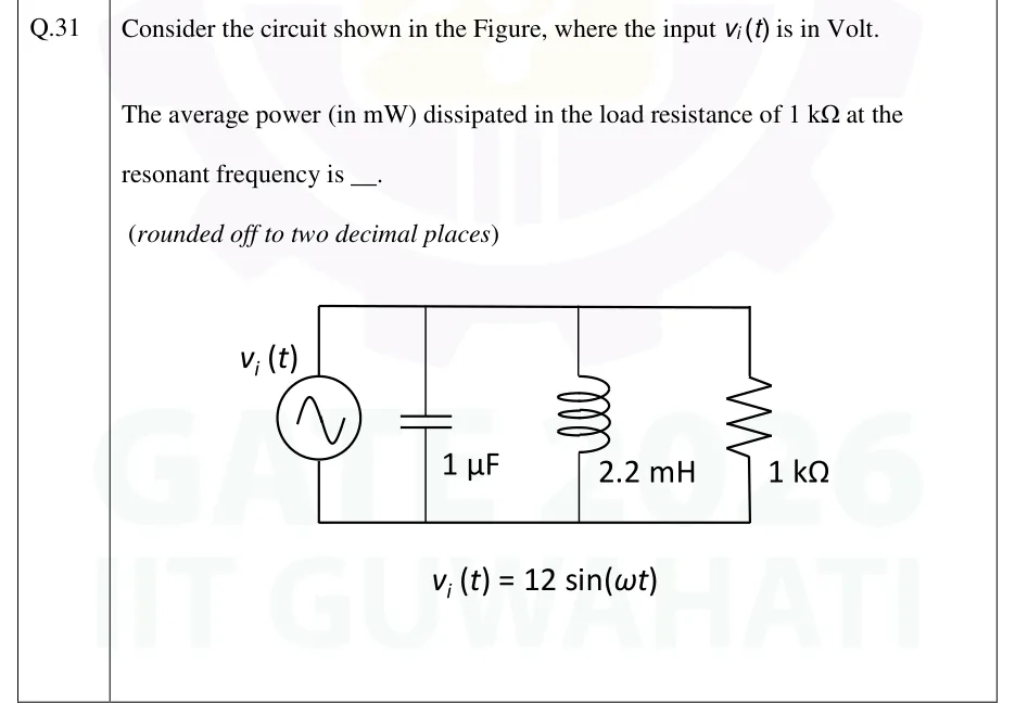
Consider the circuit shown in the Figure, where the input is in Volt.
The average power (in mW) dissipated in the load resistance of at the resonant frequency is ____. (rounded off to two decimal places)
 Tap to open full size
Figure description
An ideal sinusoidal voltage source v_i(t) (circle with a sine symbol) sits in the left vertical branch. Its top terminal connects to a top rail and its bottom terminal to a bottom rail. Three more vertical branches run between the same two rails, left to right: a 1 capacitor, a 2.2 mH inductor and a 1 k Ω resistor. There are no other elements, so the source, C, L and R are all in parallel across the same two nodes. Below the circuit it reads: v_i(t) = 12 sin (ω t).