
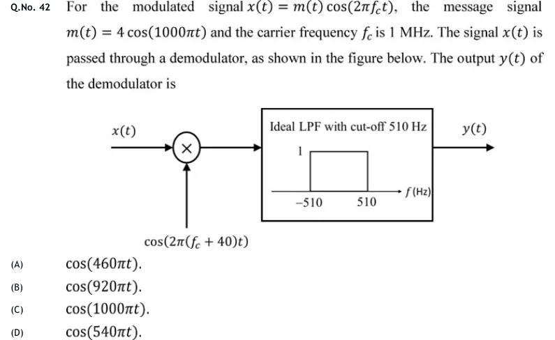
For the modulated signal , the message signal and the carrier frequency is 1 MHz. The signal is passed through a demodulator, as shown in the figure below. The output of the demodulator is
 Tap to open full size
Figure description
Block diagram: input x(t) goes into a multiplier (circle with a cross). A second input enters the multiplier from below, labelled cos(2π(f_c + 40)t). The multiplier output feeds a box labelled 'Ideal LPF with cut-off 510 Hz'. Inside the box is a plot of the frequency response, with the f (Hz) axis, a rectangular passband of height 1 from -510 to 510, and ticks at -510 and 510. The box output is y(t).
- (A)
cos(460πt).
- (B)
cos(920πt).
- (C)
cos(1000πt).
- (D)
cos(540πt).