
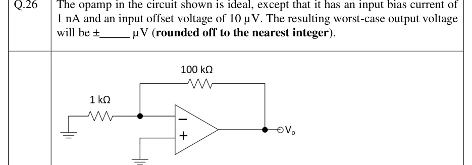
The opamp in the circuit shown is ideal, except that it has an input bias current of 1 nA and an input offset voltage of 10 V. The resulting worst-case output voltage will be ______ V (rounded off to the nearest integer).
 Tap to open full size
Figure description
Inverting-amplifier configuration with no input signal. A 1 kΩ resistor connects ground (left) to a node that goes to the op-amp's inverting (−) input. A 100 kΩ feedback resistor connects this inverting-input node to the op-amp output. The non-inverting (+) input is connected directly to ground (no resistor). The output node is labelled V_o.