
The of the circuit shown below is
 Tap to open full size
Figure description
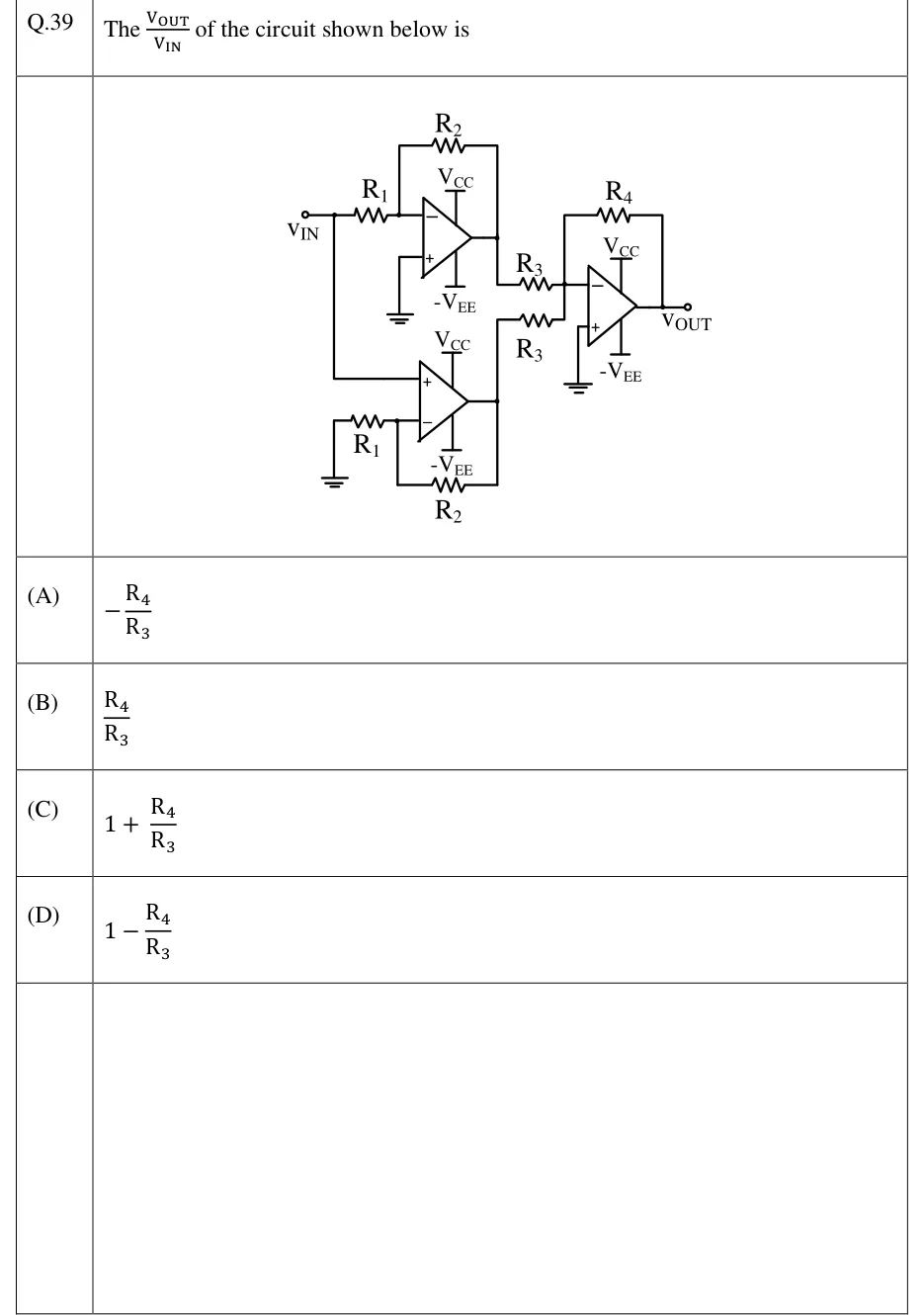
Three op-amps, each powered from V_CC (top rail) and -V_EE (bottom rail). Op-amp 1 (top left): V_IN is applied through R_1 to its inverting (−) input; R_2 is connected from its output back to the − input; its non-inverting (+) input is grounded. Op-amp 2 (bottom left): the V_IN node is also wired straight down to its non-inverting (+) input; its inverting (−) input goes to ground through R_1, and R_2 is connected from its output to the − input. Op-amp 3 (right): the output of op-amp 1 goes through a resistor R_3, and the output of op-amp 2 goes through a second resistor R_3. Both resistors join at the inverting (−) input of op-amp 3. R_4 is connected from the output of op-amp 3 back to its − input, and its + input is grounded. The output of op-amp 3 is V_OUT.
- (A)
- (B)
- (C)
- (D)