
IAE Academy

ISRO EC 2025 Q.58: solution and answer

ISRO 2025 · ECQ.58 · 1 mark · MCQ

In the circuit given below, LED will be ON (OPAMP and LED to be considered as ideal) when Vi is:
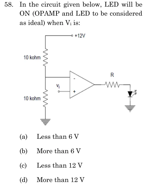
ISRO EC 2025 question 58: A resistive divider: +12 V at the top, a 10 kohm resistor, a middle node, a second 10 kohm resistor, then ground.Tap to open full size
Figure from the ISRO EC 2025 paper. It is part of the question.
Figure description

A resistive divider: +12 V at the top, a 10 kohm resistor, a middle node, a second 10 kohm resistor, then ground. The middle node connects by a wire to the inverting (-) input of an op-amp. The input source Vi is applied to the non-inverting (+) input, with its other end at the reference node. The op-amp has no feedback, so it works as a comparator. Its output goes through a series resistor R to the anode of an LED, and the LED cathode goes to ground.

  1. (A)

    Less than 6 V

  2. (B)

    More than 6 V

  3. (C)

    Less than 12 V

  4. (D)

    More than 12 V

Answer and solution

ANSWER

The LED is ON when is more than , which is option (b).

Official answer: BSource: ISRO's final answer key of 15 May 2026

  1. The two equal resistors divide the supply, so the node feeding the inverting input sits at .

  2. The op-amp has no feedback, so it works as an open-loop comparator. Its output is when and (or ) when .

  3. Here (non-inverting input) and .

  4. The LED has its anode on the op-amp output (through ) and its cathode on ground. It conducts only when the output is positive, i.e. .

  5. The output is positive when , so the LED is ON for more than .

  6. For the output is negative (or zero), so the LED is reverse biased or off. This rules out option (a).

  7. The switching point is the divider voltage, , not . Option (c) would include , where the LED is OFF, and option (d) would wrongly leave out , where the LED is also ON.

KEY IDEA

An op-amp with no feedback is a comparator: the output goes high when the non-inverting input exceeds the inverting input. Find the reference from the resistor divider, then check which output polarity forward-biases the LED.

WATCH OUT FOR

Using the supply as the threshold instead of the divider voltage of , or forgetting that the divider drives the inverting input, which would flip the condition to "less than ".

From the ISRO EC 2025 paper. Every question of this paper · The full paper (PDF, ISRO) · All 4 ISRO Filters & waveforms questions, with notes

More ISRO Filters & waveforms questions