
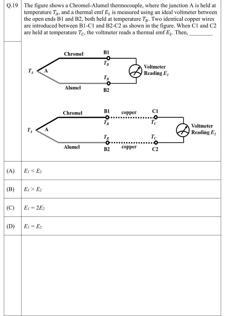
The figure shows a Chromel-Alumel thermocouple, where the junction A is held at temperature , and a thermal emf is measured using an ideal voltmeter between the open ends B1 and B2, both held at temperature . Two identical copper wires are introduced between B1-C1 and B2-C2 as shown in the figure. When C1 and C2 are held at temperature , the voltmeter reads a thermal emf . Then, ________
 Tap to open full size
Figure description
Two sketches. Top: a Chromel wire (thick black) and an Alumel wire (grey) meet at junction A at temperature T_A on the left. Their open ends B1 (Chromel, upper) and B2 (Alumel, lower), both marked at temperature T_B, connect directly to a voltmeter reading E_1. Bottom: the same thermocouple with junction A at T_A and ends B1, B2 at T_B, but now a dotted copper wire runs from B1 to C1 and another identical copper wire from B2 to C2. C1 and C2 are both marked at temperature T_C, and the voltmeter, connected across C1 and C2, reads E_2.
- (A)
- (B)
- (C)
- (D)