
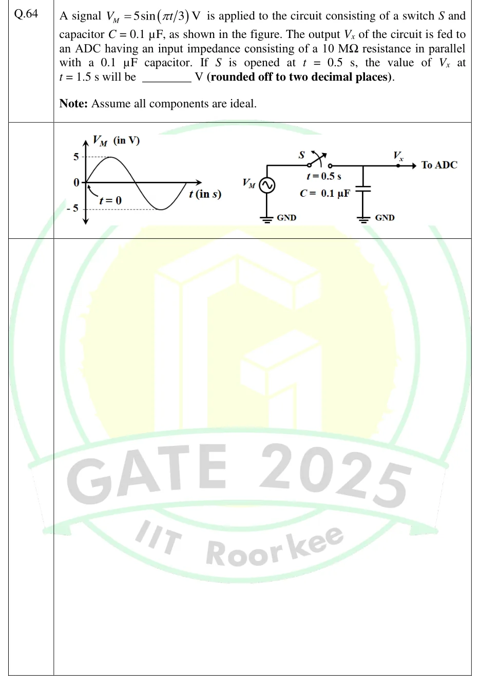
A signal V is applied to the circuit consisting of a switch and capacitor , as shown in the figure. The output of the circuit is fed to an ADC having an input impedance consisting of a resistance in parallel with a capacitor. If is opened at s, the value of at s will be ________ V (rounded off to two decimal places).
Note: Assume all components are ideal.
 Tap to open full size
Figure description
Left: a plot of V_M (in V) against t (in s). The vertical axis is marked 5, 0 and -5, with dashed guide lines at +5 and -5. The waveform is one full sine cycle. It starts at 0 at t = 0 (an arrow labelled "t = 0" points to the origin), rises to +5, returns to 0, falls to -5 and returns to 0. The time axis has no numbered ticks. Right: the circuit. An AC voltage source V_M (a circle with a sine symbol) has its bottom terminal at GND. Its top terminal runs to switch S. The switch is drawn with its blade lifted and a curved arrow across it showing the opening action, with "t = 0.5 s" printed below it. From the switch the wire runs to the output node. Capacitor C = 0.1 (label printed to its left) goes from that node to GND. The wire continues right to a solid dot labelled V_x, and an arrow from the dot is labelled "To ADC". The ADC's input impedance (10 M Ω in parallel with 0.1) is given only in the text and is not drawn.