
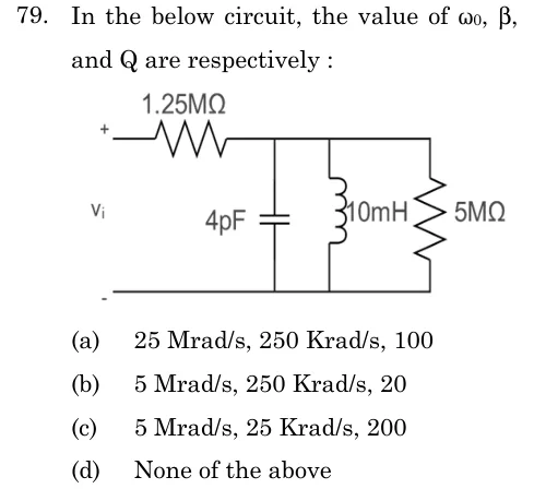
In the below circuit, the value of ω0, β, and Q are respectively :
 Tap to open full size
Figure description
Input voltage V_i applied between a top terminal (+) and a bottom terminal (-). A 1.25 MΩ resistor is in series in the top rail. After it, three parallel branches connect the top rail to the bottom rail: a 4 pF capacitor, a 10 mH inductor, and a 5 MΩ resistor.
- (A)
25 Mrad/s, 250 Krad/s, 100
- (B)
5 Mrad/s, 250 Krad/s, 20
- (C)
5 Mrad/s, 25 Krad/s, 200
- (D)
None of the above