
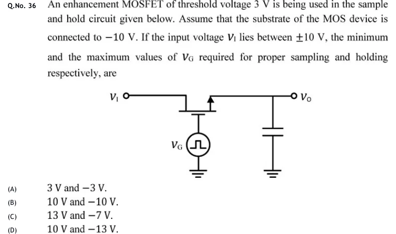
An enhancement MOSFET of threshold voltage 3 V is being used in the sample and hold circuit given below. Assume that the substrate of the MOS device is connected to V. If the input voltage lies between V, the minimum and the maximum values of required for proper sampling and holding respectively, are
 Tap to open full size
Figure description
Sample-and-hold circuit. The input terminal V_I is wired to the left channel terminal of an enhancement MOSFET. The MOSFET is drawn upside down: the channel line is horizontal at the top and the gate plate sits just below it. The right channel terminal is wired to the output terminal V_O, and that lead carries an arrow pointing away from the channel (upward). This is the simplified n-channel symbol with the arrow on the source lead. No separate substrate terminal is drawn. A capacitor runs from the V_O node to ground. The gate is driven by a pulse voltage source labelled V_G (a circle containing a single rectangular pulse), and the other end of that source is grounded. The question text says the substrate is connected to -10 V.
- (A)
3 V and V.
- (B)
10 V and V.
- (C)
13 V and V.
- (D)
10 V and V.