IAE Academy

GATE CS

Layering and switching

Circuit, packet and virtual circuit

Layering splits network communication into a stack of layers, each with one job, its own header and its own unit of data; switching decides how data crosses the links between two hosts (a dedicated circuit, independent packets, or packets along a fixed virtual path). GATE questions turn on knowing each layer's data unit and the device that works there, and on computing the end-to-end delay of a message sent whole or as several packets over several store-and-forward hops.

2 previous-year questions · 2 solved · 5 practice questions

Why protocols are layered

A network task (move a file from an application on one host to an application on another) is split into layers. Each layer offers a service to the layer above, uses the service of the layer below, and talks to its peer layer on the other machine through a protocol. Only the service interface is visible between layers, so one layer can be replaced (say, Wi-Fi for Ethernet) without touching the rest.

What layering gives

  1. Modularity: each layer solves one problem (reliability, addressing, medium access).

  2. Independence: a layer's internals can change while its service stays the same.

  3. Easier standardisation and troubleshooting: a fault can be assigned to a layer.

  4. Cost: every layer adds a header (overhead), and some work is repeated at several layers.

Data moves down the stack at the sender, each layer adding its own header (encapsulation), across the medium, and up the stack at the receiver, each layer removing the header meant for it (decapsulation).

OSI and TCP/IP models

OSI layer

Name

Unit of data (PDU)

What it does

7

Application

Message / data

Services used directly by programs

6

Presentation

Message / data

Data representation, encoding, encryption, compression

5

Session

Message / data

Dialogue control, synchronisation points

4

Transport

Segment (TCP) / datagram (UDP)

Process-to-process delivery, ports, reliability, flow and congestion control

3

Network

Packet

Host-to-host delivery across networks: logical (IP) addressing, routing

2

Data link

Frame

Delivery across one link: physical (MAC) addressing, framing, error detection, medium access

1

Physical

Bit

Sends raw bits as signals over the medium

TCP/IP layer

Covers OSI layers

Typical protocols

Application

5, 6, 7

HTTP, SMTP, DNS, FTP

Transport

4

TCP, UDP

Internet

3

IP, ICMP

Link (network access)

2 and 1

Ethernet, Wi-Fi

Convention: the TCP/IP model is drawn with four layers, or with five if the link layer is split into data link and physical. OSI is a reference model with seven layers; the Internet actually runs TCP/IP. Addressing at each level: the application layer uses names such as domain names or e-mail addresses, the transport layer uses port numbers, the network layer uses IP addresses, the data link layer uses MAC addresses.

EXAM TIP

Remember the unit by layer from the bottom: bit, frame, packet, segment, then data. CRC-based error detection on each link is a data link job (TCP, UDP and the IPv4 header also carry checksums), routing is a network job, end-to-end reliability is a transport job.

Encapsulation, header overhead and devices

At the sender, the application data gets a transport header to form a segment, the segment gets a network header to form a packet, and the packet gets a data link header (and usually a trailer carrying the CRC) to form a frame; the physical layer sends the frame as bits and adds no header. The receiver strips the headers in reverse order. What a layer receives from the layer above is its SDU (its payload); the SDU plus that layer's header is the layer's PDU.

HEADER EFFICIENCY

Fraction of transmitted bits that is useful data; with several layers, add up the headers of all layers that wrap the payload.

Device

Works up to layer

Forwards using

Domains

Repeater / hub

1 (physical)

Nothing: regenerates bits on all other ports

One collision domain and one broadcast domain for all ports

Bridge / layer-2 switch

2 (data link)

MAC address (learns it from source addresses)

Each port is its own collision domain; one broadcast domain (without VLANs)

Router

3 (network)

IP address, using a routing table

Each interface is its own collision and broadcast domain

Gateway

Up to 7

Protocol translation

Depends on the device

EXAM TIP

A device that works at layer n processes the headers of layers 1 to n only. A switch reads the MAC header but does not change it. A router writes a new data link header at every hop (new source and destination MAC) but leaves the source and destination IP addresses unchanged; in the IPv4 header it only decrements the TTL and recomputes the header checksum (and may fragment), unless it performs NAT.

EXAM TIP

Header sizes commonly asked (minimum, no options): TCP 20 bytes, UDP 8 bytes, IPv4 20 bytes, IPv6 base header 40 bytes, Ethernet header 14 bytes plus 4 bytes CRC (the 8 bytes of preamble and SFD are counted only if the question says so). Use the sizes the question gives; 1 byte = 8 bits.

Circuit switching

In circuit switching a dedicated path is set up between the two hosts before any data is sent. Along the path each link carries the call in its own share of capacity: a frequency band (FDM) or a repeating time slot (TDM). The resources stay reserved for the whole call, used or not, and are released at teardown.

Phases of a call

  1. Circuit establishment: a request travels hop by hop reserving a channel on each link; the acknowledgement comes back.

  2. Data transfer: bits flow over the reserved channel at a fixed rate, in order, with no queueing and no addresses in the data.

  3. Circuit release: the channels are freed.

If a link of rate is shared by circuits by TDM or FDM, each circuit ideally (ignoring guard bands and framing overhead) gets . Because the path is dedicated, data is not stored and forwarded at each switch: only the propagation delay accumulates along the path, and the message is transmitted once.

MESSAGE DELAY IN A CIRCUIT-SWITCHED NETWORK

L = message size in bits, R = rate of the reserved circuit in bits per second (R/n of the link rate when n circuits share it); T_setup is the set-up time given in the question (teardown ignored); T_prop,path is the sum of the propagation delays of all links. Switch processing is ignored unless stated.

WORKED EXAMPLE

A circuit-switched link of 2.048 Mbps (1 Mbps = 10^6 bits per second) is divided by TDM into 32 slots, one per circuit. A 320,000-bit file is sent over one circuit. Circuit set-up takes 250 ms; propagation delay is negligible. How long does the transfer take from the start of set-up?

Solution
  1. Rate of one circuit: 2.048 x 10^6 / 32 = 64,000 bits per second.

  2. Transmission time: 320,000 / 64,000 = 5 s.

  3. T = 0.25 + 5 = 5.25 s.

Answer: 5.25 s

Strengths: guaranteed rate and constant delay, in-order delivery, no per-packet header. Weakness: idle capacity is wasted during silences, set-up time is paid even for short transfers, and a call can be blocked if no channel is free.

Packet switching: datagram and virtual circuit

In packet switching the message is cut into packets that share the links on demand (statistical multiplexing). Every switch stores a whole packet, then forwards it (store-and-forward; assume this unless the question says cut-through); a packet waits in a queue if the outgoing link is busy. No capacity is reserved, so queueing delay and packet loss are possible.

Datagram (connectionless) switching. No set-up. Each packet carries the full destination address, and each router looks it up in its forwarding table independently; routers keep no per-connection state. Packets of one message may take different routes, arrive out of order, or be lost. If a router fails, packets queued at it or sent to it are lost, and later packets can be routed around it once the forwarding tables are updated.

Virtual-circuit switching (connection-oriented). A set-up phase fixes one route and assigns a virtual-circuit identifier (VCI) on every link of it. Each packet carries only a short VCI, not the full address; each switch looks up (incoming port, incoming VCI) in its table, which gives the outgoing port and the outgoing VCI, and swaps in the outgoing VCI. All packets follow the same path and arrive in order. Unlike circuit switching, the path is logical: capacity may or may not be reserved, and packets are still stored and forwarded and can queue. X.25, Frame Relay and ATM are virtual-circuit networks.

Feature

Circuit switching

Datagram

Virtual circuit

Set-up before data

Yes

No

Yes

Path

Dedicated, physical

Each packet chooses (per router table)

One fixed route for the whole connection

Routing decision

At set-up

For every packet

At set-up

Per-connection state in switches

Yes

No

Yes

Resources reserved

Yes, for the whole call

No

Not necessarily

Store-and-forward at each hop

No

Yes

Yes

Address in each unit

None after set-up

Full destination address

Short VC identifier

Order of delivery

In order

May be reordered

In order

Queueing delay and loss

None once connected

Possible

Possible

Router/switch failure

Call is dropped

Later packets reroute

Circuit is broken and must be re-set up

Efficiency for bursty traffic

Poor

Good

Good

EXAM TIP

Do not confuse 'virtual circuit' with 'circuit switching'. A virtual circuit still uses store-and-forward packets with queueing; only the route and the order are fixed. Also, the IP network layer is datagram; TCP gives a reliable connection on top of it without making the network connection-oriented.

Delay of a message over several hops

Per link, the delay of one packet is : transmission delay (pushing all bits onto a link of rate ), propagation delay (signal travel time over distance at the speed given), plus processing and queueing delay, which are zero unless the question gives them. Convention: bits per second and bits per second for rates; sizes use the unit stated, with 1 byte = 8 bits. A path with links has intermediate switches or routers.

ONE PACKET OVER K LINKS (STORE-AND-FORWARD)

The whole packet is transmitted again on every link, so transmission delay is counted k times; all links at rate R, no queueing or processing. If the links have different propagation delays, add the delays given.

A MESSAGE SENT AS N EQUAL PACKETS OVER K LINKS

Each packet has p bits including its header, all links at rate R, no queueing, and the packets go back to back. The first packet needs k transmission times; each later packet arrives one transmission time after the one before it (pipelining). T is the time from the first bit leaving the source until the last bit of the last packet reaches the destination.

N EQUAL PACKETS OVER LINKS OF DIFFERENT RATES

R_i = rate of link i, R_min = rate of the slowest link (the bottleneck). The first packet crosses every link once; the later packets leave the bottleneck one p/R_min apart and keep that spacing. With all rates equal this reduces to the previous formula. No other traffic, no queueing apart from waiting for the packet ahead.

PAYLOAD SIZE THAT MINIMISES TOTAL DELAY

M = message bits, h = header bits per packet, k >= 2 links of equal rate, ignoring the rounding of M/x to a whole number. Derivation: delay times R is (k-1+M/x)(x+h) = (k-1)x + (k-1)h + M + Mh/x; setting its derivative with respect to x to zero gives (k-1) = Mh/x^2. Propagation does not depend on x.

Why more packets help: with one big packet (message switching) every hop waits for the full message, giving when headers are ignored. Splitting lets hops work in parallel, giving about . Too many packets, however, mean more headers and more bits to send, so there is an optimum.

WORKED EXAMPLE

A 9000-bit message goes from host A to host B over 3 links, each of rate 1 Mbps with propagation delay 2 ms. Ignore queueing and processing; there are no headers except in (c). Find the delay (a) sending it as one packet, (b) as 9 packets of 1000 bits, (c) as 9 packets of 1000 payload bits each with a 100-bit header, and (d) by circuit switching over a circuit of 1 Mbps end to end with a 20 ms set-up time.

Solution
  1. Total propagation along the path: 3 x 2 ms = 6 ms for every case.

  2. (a) Transmission time of the whole message on one link: 9000 / 10^6 = 9 ms. T = 3 x 9 + 6 = 33 ms.

  3. (b) One packet takes 1000 / 10^6 = 1 ms per link. T = (3 + 9 - 1) x 1 + 6 = 11 + 6 = 17 ms.

  4. (c) Each packet is 1100 bits, so 1.1 ms per link. T = 11 x 1.1 + 6 = 12.1 + 6 = 18.1 ms.

  5. (d) No store-and-forward: the message is sent once at 1 Mbps, 9 ms. T = 20 + 9 + 6 = 35 ms.

Answer: (a) 33 ms, (b) 17 ms, (c) 18.1 ms, (d) 35 ms

WORKED EXAMPLE

A datagram network sends a 6000-bit message over 4 links of rate 2 Mbps each. Propagation and queueing delay are negligible. Packets have 500-bit headers. If the message is split into packets of 1000 payload bits, what is the delay?

Solution
  1. Number of packets: 6000 / 1000 = 6.

  2. Packet size: 1000 + 500 = 1500 bits; time per link: 1500 / (2 x 10^6) = 0.75 ms.

  3. T = (k + n - 1) x 0.75 ms = (4 + 6 - 1) x 0.75 = 9 x 0.75 = 6.75 ms.

Answer: 6.75 ms

WORKED EXAMPLE

Three packets of 1000 bits each are sent back to back over two links in series: link 1 at 1 Mbps, then link 2 at 0.5 Mbps. Propagation, processing and queueing at the source are negligible. When does the last bit reach the destination?

Solution
  1. Per-packet times: 1000 / 10^6 = 1 ms on link 1, 1000 / (0.5 x 10^6) = 2 ms on link 2 (the bottleneck).

  2. Formula: T = (1 + 2) + (3 - 1) x 2 = 7 ms.

  3. Timeline check: link 1 finishes the packets at 1, 2, 3 ms; link 2 sends packet 1 from 1 to 3 ms, packet 2 from 3 to 5 ms, packet 3 from 5 to 7 ms.

Answer: 7 ms

EXAM TIP

Check what the question counts: if it says 'links', use k links; if it says 'intermediate routers', then links = intermediate routers + 1. For circuit switching count the transmission once; for packet switching count (k + n - 1) packet times. If the packets are unequal (a short last packet), do not use the formula blindly: draw the timeline hop by hop.

PREVIOUS-YEAR QUESTIONS

2 questions from the CS papers

Try each question first, then open the answer. We placed each question under a topic ourselves; the exam paper does not label topics.

See these papers in full: GATE CSE 2025 Set 1 · GATE CSE 2018

GATE 2025 CS1 Q.16

GATE 2025 · CS1Q.16 · 1 mark · MCQ

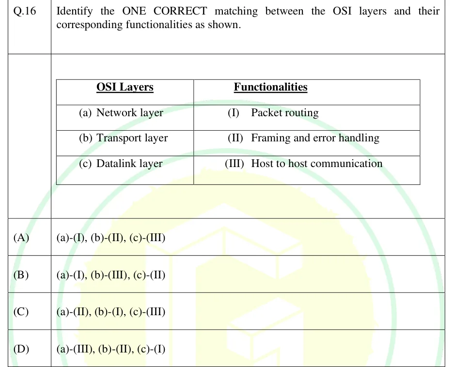
Identify the ONE CORRECT matching between the OSI layers and their corresponding functionalities as shown.

GATE 2025 CS1 question 16: A two-column table.Tap to open full size
Figure from the GATE 2025 CS1 paper. It is part of the question.
Figure description

A two-column table. Header: OSI Layers | Functionalities. Rows: (a) Network layer | (I) Packet routing; (b) Transport layer | (II) Framing and error handling; (c) Datalink layer | (III) Host to host communication.

  1. (A)

    (a)-(I), (b)-(II), (c)-(III)

  2. (B)

    (a)-(I), (b)-(III), (c)-(II)

  3. (C)

    (a)-(II), (b)-(I), (c)-(III)

  4. (D)

    (a)-(III), (b)-(II), (c)-(I)

Answer and solution
GATE 2025 CS1 Q.16: answer and solution

OTHER EXAMS

ISRO: 2 questions

From ISRO's Scientist/Engineer written test: ISRO CS 2025, ISRO CS 2023. They are not counted in the GATE numbers on this page.

ISRO CS 2023 Q.14

ISRO 2023 · CSQ.14 · 1 mark · MCQ

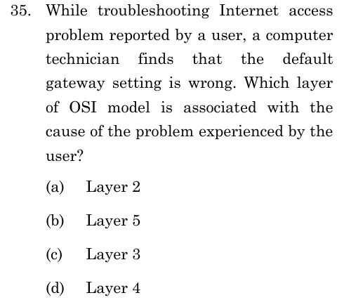
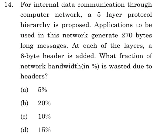
For internal data communication through computer network, a 5 layer protocol hierarchy is proposed. Applications to be used in this network generate 270 bytes long messages. At each of the layers, a 6-byte header is added. What fraction of network bandwidth (in %) is wasted due to headers?

  1. (A)

    5%

  2. (B)

    20%

  3. (C)

    10%

  4. (D)

    15%

Answer and solution
See the question in the paper
ISRO CS 2023 Q.14: answer and solution

PRACTICE

5 questions to test yourself

PRACTICE 11 mark · MSQ

Which of the following statements are correct?

  1. (A)

    A hub regenerates incoming bits on all other ports, so all hosts on it share one collision domain.

  2. (B)

    A layer-2 switch forwards frames using MAC addresses and gives each port its own collision domain.

  3. (C)

    Each interface of a router belongs to a separate broadcast domain.

  4. (D)

    A hub examines the destination MAC address of a frame before forwarding it.

Answer and solution

Answer: (A), (B), (C)

  1. A hub is a physical-layer device: it only repeats bits, so all ports form one collision domain. A is correct.

  2. A switch works at the data link layer, learns MAC addresses and isolates collisions per port. B is correct.

  3. A router does not forward broadcast frames; each interface is a separate broadcast domain. C is correct.

  4. A hub does not read any address. D is false.

PRACTICE 21 mark · NAT

An 8000-bit packet is sent from a source to a destination over 4 links in series, each of rate 2 Mbps (1 Mbps = 10^6 bits per second). Propagation, queueing and processing delays are negligible and the switches use store-and-forward. Find the end-to-end delay in milliseconds.

Answer and solution

Answer:

  1. Transmission time per link: 8000 / (2 x 10^6) = 4 ms.

  2. The whole packet is received and retransmitted at each hop, so 4 transmissions.

  3. T = 4 x 4 = 16 ms.

PRACTICE 32 marks · NAT

A 24000-bit message is split into packets each carrying 2000 payload bits plus a 400-bit header. The packets are sent back to back over 3 links in series (two intermediate store-and-forward routers), each link of rate 1.2 Mbps (1 Mbps = 10^6 bits per second). Propagation, queueing and processing delays are zero. Find the time in milliseconds from the first bit leaving the source until the last bit reaches the destination.

Answer and solution

Answer:

  1. Number of packets n = 24000 / 2000 = 12.

  2. Packet size = 2400 bits; time per link = 2400 / (1.2 x 10^6) = 2 ms.

  3. T = (k + n - 1) x 2 ms = (3 + 12 - 1) x 2 = 28 ms.

PRACTICE 41 mark · MCQ

Which statement about a virtual-circuit network is correct?

  1. (A)

    Every packet carries the full destination address and is routed independently.

  2. (B)

    All packets of a connection follow the same route, arrive in order, and carry a short circuit identifier that is changed from link to link.

  3. (C)

    Capacity is always reserved on every link for the whole duration of the connection, as in circuit switching.

  4. (D)

    Packets are not stored at the switches, so there is no queueing delay.

Answer and solution

Answer: (B)

  1. A describes datagram switching, not virtual circuits.

  2. B is correct: the route is fixed at set-up, the table at each switch maps (incoming port, VCI) to (outgoing port, outgoing VCI), and order is preserved.

  3. C is false: reservation is possible but not required; it is the defining feature of circuit switching.

  4. D is false: virtual-circuit packets are still stored and forwarded and can queue.

PRACTICE 52 marks · NAT

A 90000-bit message is sent over 10 links in series of equal rate using store-and-forward packet switching. Each packet has a 100-bit header. Ignoring the rounding of the number of packets to a whole number and ignoring propagation delay, what payload size in bits per packet minimises the total delay?

Answer and solution

Answer:

  1. Delay x R = (k + M/x - 1)(x + h) with k = 10, M = 90000, h = 100.

  2. Expanding: (k-1)x + (k-1)h + M + Mh/x. Setting the derivative to zero: (k-1) = Mh / x^2.

  3. x = sqrt(M h / (k-1)) = sqrt(90000 x 100 / 9) = sqrt(1000000) = 1000 bits.

OFFICIAL GATE 2027 SYLLABUS WORDING

Copied from the GATE 2027 syllabus; see all 2027 syllabi.

GATE CS

Principles of Layering; Basics of switching (circuit, packet and virtual circuit)

Preparing in Kolkata? IAE Academy's course for GATE CSE.