
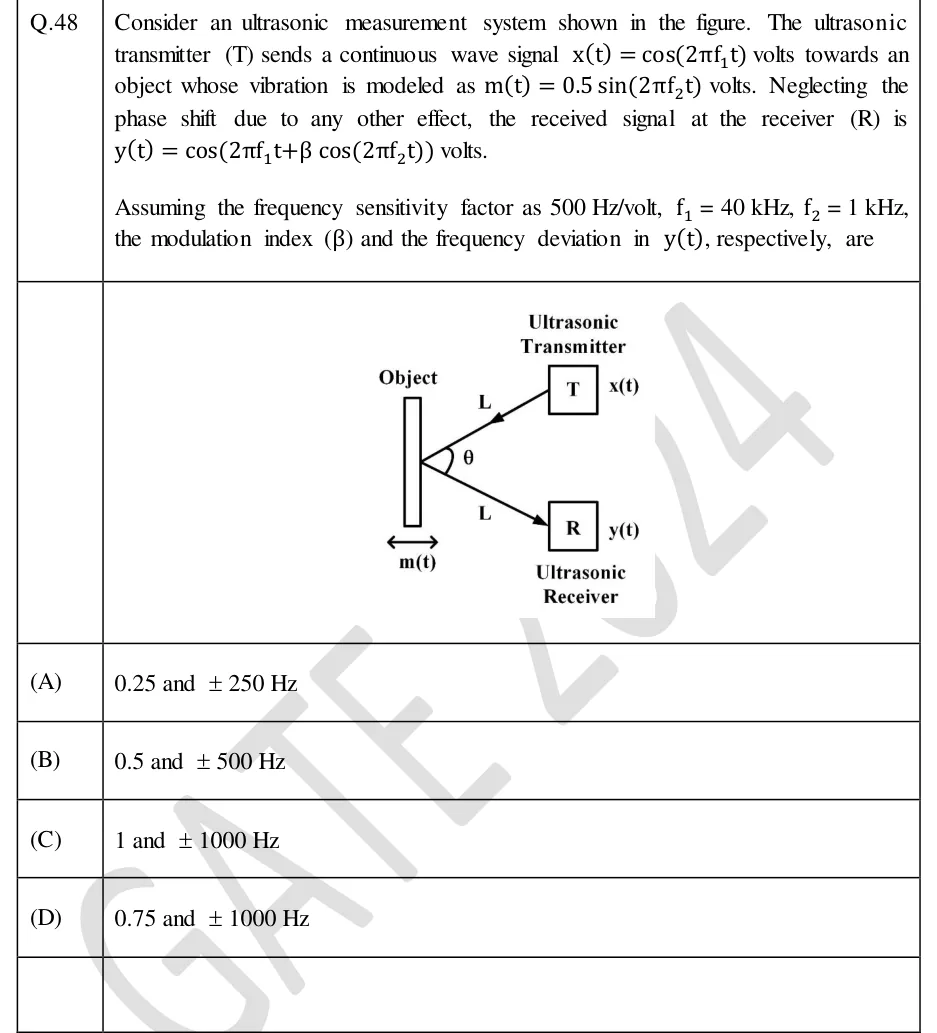
Consider an ultrasonic measurement system shown in the figure. The ultrasonic transmitter (T) sends a continuous wave signal volts towards an object whose vibration is modeled as volts. Neglecting the phase shift due to any other effect, the received signal at the receiver (R) is volts. Assuming the frequency sensitivity factor as 500 Hz/volt, kHz, kHz, the modulation index () and the frequency deviation in , respectively, are
 Tap to open full size
Figure description
A transmitter block T (top right, labelled Ultrasonic Transmitter) emits x(t) along a path of length L toward a vertical rectangular Object on the left. The object can move horizontally, shown by a double-headed arrow labelled m(t). The reflected path, also of length L, goes from the object to a receiver block R (bottom right, labelled Ultrasonic Receiver) producing y(t). The angle between the incident and reflected paths at the object is labelled theta.
- (A)
0.25 and ±250 Hz
- (B)
0.5 and ±500 Hz
- (C)
1 and ±1000 Hz
- (D)
0.75 and ±1000 Hz