
IAE Academy

GATE 2025 EC Q.21: solution and answer

GATE 2025 · ECQ.21 · 1 mark · MCQ

A simplified small-signal equivalent circuit of a BJT-based amplifier is given below.

The small-signal voltage gain (in V/V) is ________.
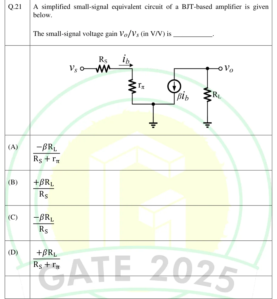
GATE 2025 EC question 21: Small-signal hybrid-pi circuit.Tap to open full size
Figure from the GATE 2025 EC paper. It is part of the question.
Figure description

Small-signal hybrid-pi circuit. Input side: source terminal v_s (open circle) connects through series resistor R_S to a node; an arrow labelled i_b points rightwards along the wire after R_S, into that node. From that node, resistor r_π goes vertically down to a bottom node that is grounded (ground symbol below a junction dot). Output side: the same grounded bottom node connects to the bottom terminal of a dependent current source labelled β i_b; the arrow inside the source points DOWNWARD (current flows from the top terminal to the bottom/ground terminal). The top terminal of the current source connects to the output node v_o (junction dot, open-circle output terminal labelled v_o). From the output node, load resistor R_L goes down to a separate ground symbol. There is no direct connection between the input node and the output node other than through ground.

  1. (A)

  2. (B)

  3. (C)

  4. (D)

Answer and solution

ANSWER

, which is option (A).

Official answer: ASource: Official answer key, GATE 2025 EC (IIT Roorkee)

  1. Model as drawn: the transistor appears as its hybrid-pi input resistance and a dependent current source . No output resistance is drawn, so it is taken as infinite (open circuit). The input and output halves are joined only through the common ground.

  2. KVL around the input loop ( ground). The same current flows through and : , so

  3. Direction of the dependent source: its arrow points down, so the current enters the source's top terminal from the node and leaves at the bottom terminal into ground. In other words, the source pulls out of the output node.

  4. KCL at the output node, summing currents leaving it:

  5. Substitute from step 2:

  6. The gain is negative, because current pulled out of the load node inverts the phase as in a common-emitter stage. Its magnitude has in the denominator. That is option (A).

KEY IDEA

The source resistance and are in series, so . The dependent source forces through , which gives . The source arrow points away from the output node, so the output voltage is negative.

WATCH OUT FOR

One mistake is to drop from the input loop and write , which leads to option (C). The other is to misread the source's direction and lose the minus sign, which leads to (D). The downward arrow means the source pulls current OUT of the node through from ground, so is negative.

From the GATE 2025 EC paper. Every question of this paper · Download the full paper · All 20 Amplifiers questions, with notes

More Amplifiers questions