
IAE Academy

ISRO EC 2025 Q.59: solution and answer

ISRO 2025 · ECQ.59 · 1 mark · MCQ

Consider the circuit shown below. This amplifier circuit will be
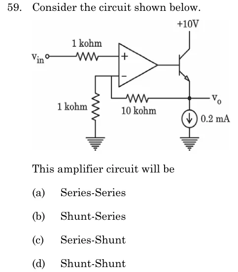
ISRO EC 2025 question 59: An op-amp with its non-inverting (+) input fed from V_in through a 1 kΩ series resistor.Tap to open full size
Figure from the ISRO EC 2025 paper. It is part of the question.
Figure description

An op-amp with its non-inverting (+) input fed from V_in through a 1 kΩ series resistor. The op-amp output drives the base of an NPN transistor whose collector is tied to +10 V. The transistor emitter is the output node V_o, and a 0.2 mA current source sinks current from V_o to ground (bias for the emitter follower). A 10 kΩ resistor runs from V_o back to the inverting (−) input node, and a 1 kΩ resistor connects that inverting node to ground.

  1. (A)

    Series-Series

  2. (B)

    Shunt-Series

  3. (C)

    Series-Shunt

  4. (D)

    Shunt-Shunt

Answer and solution

ANSWER

The amplifier is a series-shunt feedback amplifier (voltage-series feedback), option (C).

Official answer: CSource: ISRO's final answer key of 15 May 2026

  1. The op-amp drives the base of an NPN emitter follower biased by a current source, and is the emitter voltage. The follower sits inside the loop, so the whole block acts as a non-inverting amplifier with applied to the input and the divider / returned to the input.

  2. Feedback network: the resistor runs from to the inverting node and the resistor from that node to ground, so

  3. Sampling at the output: the feedback network is connected directly across the output node , in parallel with the load. If is set to , the feedback signal disappears, so the quantity sampled is the output voltage. This is voltage sampling, which is a shunt connection at the output.

  4. Mixing at the input: is applied to the terminal and to the terminal, so the two voltages are in series around the differential input loop: A voltage subtracted in series is series mixing, and the feedback signal is a voltage.

  5. Series mixing at the input with shunt (voltage) sampling at the output gives the series-shunt topology, a voltage amplifier. Check: a stable voltage gain set only by the resistor ratio.

  6. The other options fail. Series-series would sample the output current through a series resistor. Shunt-series and shunt-shunt need a feedback current summed at the input node, but here the feedback is a voltage applied to a separate input terminal.

KEY IDEA

Identify the topology by two tests. At the output, set : if the feedback vanishes, the sampling is of voltage (shunt). At the input, ask whether the feedback is subtracted as a voltage in series with the source (series mixing) or as a current at a node (shunt mixing). Here the feedback is a voltage in series and it is sampled from , giving series-shunt.

WATCH OUT FOR

Treating the emitter follower and current source as the feedback element, or naming the topology by the type of feedback signal alone. The first letter of the pair is the mixing at the input (series) and the second is the sampling at the output (shunt), and the order is easy to swap.

From the ISRO EC 2025 paper. Every question of this paper · The full paper (PDF, ISRO) · All 2 ISRO Feedback & oscillators questions, with notes