
IAE Academy

GATE 2024 EC Q.50: solution and answer

GATE 2024 · ECQ.50 · 2 marks · MCQ

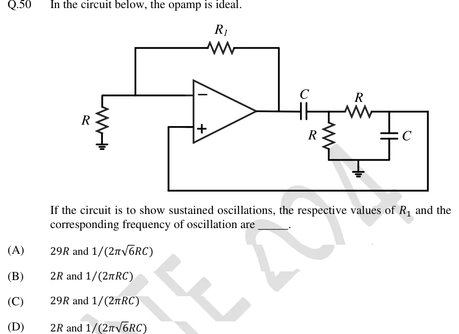
In the circuit below, the opamp is ideal.

[Figure]

If the circuit is to show sustained oscillations, the respective values of and the corresponding frequency of oscillation are _____.
GATE 2024 EC question 50: An op-amp with its inverting (-) input on top and non-inverting (+) input below.Tap to open full size
Figure from the GATE 2024 EC paper. It is part of the question.
Figure description

An op-amp with its inverting (-) input on top and non-inverting (+) input below. The inverting input goes to ground through a resistor R, and a feedback resistor R_1 connects the inverting input to the op-amp output. So the op-amp is a non-inverting amplifier with gain 1 + R_1/R. From the output, a series capacitor C goes to node A. A resistor R connects node A to ground. A series resistor R goes from node A to node B. A capacitor C connects node B to ground. Node B is wired back along the bottom of the drawing to the non-inverting (+) input of the op-amp. The feedback network is therefore series C, shunt R, series R, shunt C (a high-pass CR section followed by a low-pass RC section). The ideal op-amp's + input draws no current, so node B is unloaded.

  1. (A)

    and

  2. (B)

    and

  3. (C)

    and

  4. (D)

    and

Answer and solution

ANSWER

The answer is (B): and .

Official answer: BSource: Official answer key, GATE 2024 EC (IISc Bengaluru)

  1. Amplifier. Take the op-amp as ideal. runs from the inverting input to ground and runs from the output back to the inverting input, so this is a non-inverting amplifier: , a real, positive gain with phase .

  2. Feedback network, second section. An ideal op-amp's input draws no current, so nothing loads node B. The series and shunt form a plain voltage divider: , where .

  3. Impedance at node A. Looking from node A, the shunt to ground is in parallel with the branch :

  4. First section. The series capacitor has impedance , and it forms a divider with :

  5. Overall feedback factor. Multiply the two sections: Now put :

  6. Barkhausen phase condition. The amplifier adds , so must also have phase, which means it must be real and positive. The numerator is purely imaginary, so the denominator must be purely imaginary as well: . That gives , or .

  7. Barkhausen magnitude condition. At , , which is real and positive as required. Setting gives , so .

  8. So and , which is option (B).

KEY IDEA

The amplifier is non-inverting, so it adds of phase. The feedback path is a CR high-pass section followed by an unloaded RC low-pass section, which together act as a band-pass network with . That network has zero phase at , where . Sustained oscillation therefore needs a gain of exactly 3, which means . The numbers match the Wien-bridge oscillator.

WATCH OUT FOR

The usual mistake is to see alternating R and C sections and assume a phase-shift oscillator. That leads to a gain of 29 and , which are options (A) and (C). Those results belong to an inverting amplifier with three identical ladder sections giving . Here there are only two sections, one high-pass and one low-pass, and the amplifier is non-inverting, so the network must supply , not . A second mistake is to multiply the two sections' unloaded transfer functions together. That ignores how the second section loads node A: it gives and instead of the correct .

From the GATE 2024 EC paper. Every question of this paper · Download the full paper · All 4 Feedback & oscillators questions, with notes

More Feedback & oscillators questions