
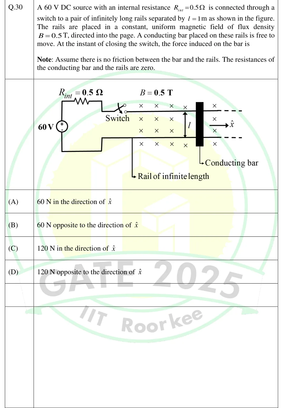
A 60 V DC source with an internal resistance is connected through a switch to a pair of infinitely long rails separated by as shown in the figure. The rails are placed in a constant, uniform magnetic field of flux density , directed into the page. A conducting bar placed on these rails is free to move. At the instant of closing the switch, the force induced on the bar is
Note: Assume there is no friction between the bar and the rails. The resistances of the conducting bar and the rails are zero.
 Tap to open full size
Figure description
A 60 V DC source is on the left, with its + terminal at the top and its - terminal at the bottom. From the + terminal a wire goes up, then right through a resistor labelled R_int = 0.5 Ohm, then down a little into a switch (drawn open) at the left end of the upper of two horizontal parallel rails. From the - terminal a wire goes down, then right, then up into the lower rail. The rails are a distance l apart, marked with a double-headed vertical arrow. They run off to the right with dashed ends, meaning they are infinitely long, and one is labelled 'Rail of infinite length'. A vertical conducting bar, drawn as a thick black rectangle, lies across both rails to the right of the l arrow and is labelled 'Conducting bar'. The region is filled with 'x' symbols (above, between and below the rails, on both sides of the bar), meaning a uniform magnetic field, labelled B = 0.5 T, directed into the page. A unit vector x-hat is drawn to the right of the bar, pointing right along the rails.
- (A)
60 N in the direction of
- (B)
60 N opposite to the direction of
- (C)
120 N in the direction of
- (D)
120 N opposite to the direction of