IAE Academy

GATE 2023 IN Q.15: solution and answer

GATE 2023 · INQ.15 · 1 mark · MCQ

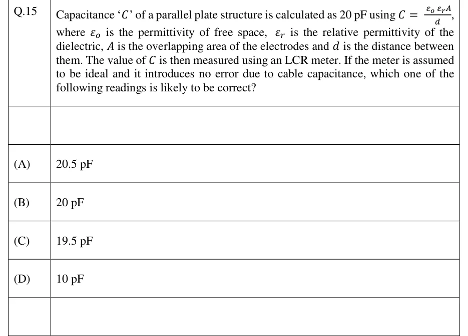
Capacitance '' of a parallel plate structure is calculated as 20 pF using , where is the permittivity of free space, is the relative permittivity of the dielectric, is the overlapping area of the electrodes and is the distance between them. The value of is then measured using an LCR meter. If the meter is assumed to be ideal and it introduces no error due to cable capacitance, which one of the following readings is likely to be correct?

  1. (A)

    20.5 pF

  2. (B)

    20 pF

  3. (C)

    19.5 pF

  4. (D)

    10 pF

See the question in the paper

Answer and solution

ANSWER

The measured value is slightly higher than the 20 pF that gives, because of fringing fields at the plate edges, so the likely reading is 20.5 pF (option A).

Official answer: ASource: Official answer key, GATE 2023 IN (IIT Kanpur)

  1. What the formula assumes. comes from Gauss's law with a uniform field that exists only in the region between the plates and nowhere else. It ignores what happens at the edges of the plates. This is exact only for infinitely large plates.

  2. What a real structure does. Real plates have a finite size, so they have fringing fields: flux lines bulge outward past the edges, and some flux also links the outer (back) faces of the plates. Each of these lines ends on charge held by the electrodes, so at the same applied voltage the plates hold more charge than the ideal model gives.

  3. Direction of the error. Since and the fringing flux adds charge at the same , So the true capacitance of a finite parallel-plate structure is always slightly greater than the value from the formula.

  4. Size of the error. In a practical parallel-plate structure the gap is small compared with the plate dimensions, so fringing adds only a small correction, typically a few percent. The true value is therefore just above 20 pF, not far above it.

  5. Eliminate options. The question says the meter is ideal and that cable capacitance adds no error, so the reading equals the true capacitance of the structure. (B) 20 pF would mean no fringing at all, which happens only for infinite plates. (C) 19.5 pF is off in the wrong direction, because fringing adds charge and cannot lower . (D) 10 pF is a 50% drop, which no edge effect can produce. That leaves 20.5 pF, option (A).

KEY IDEA

assumes a uniform field confined between infinitely large plates. Real plates have fringing flux at the edges and on the outer faces, and that flux stores extra charge at the same voltage. So the real capacitance is always a little above the formula value. With meter and cable errors excluded, a correct reading is slightly more than 20 pF.

WATCH OUT FOR

Choosing 20 pF because the meter is called ideal. An ideal meter shows the true capacitance of the structure, and the formula itself is the approximation because it leaves out fringing. The second trap is 19.5 pF, which treats the difference as random scatter. Fringing always adds capacitance, so the error has a known direction.

From the GATE 2023 IN paper. Every question of this paper · Download the full paper · All 23 Electrostatics questions, with notes

More Electrostatics questions