
IAE Academy

GATE 2023 EE Q.22: solution and answer

GATE 2023 · EEQ.22 · 1 mark · MCQ

The four stator conductors (A, A′, B and B′) of a rotating machine are carrying DC currents of the same value, the directions of which are shown in the figure (i). The rotor coils - and - are formed by connecting the back ends of conductors '' and '' and '' and '', respectively, as shown in figure (ii). The e.m.f. induced in coil - and coil - are denoted by and , respectively. If the rotor is rotated at uniform angular speed rad/s in the clockwise direction then which of the following correctly describes the and ?
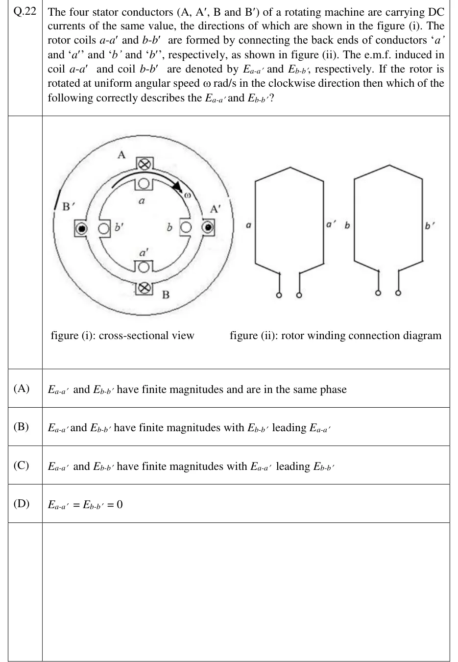
GATE 2023 EE question 22: Two sub-figures.Tap to open full size
Figure from the GATE 2023 EE paper. It is part of the question.
Figure description

Two sub-figures. Figure (i), cross-sectional view: an outer stator ring and an inner rotor ring share a common centre. Going clockwise from the top, the outer (stator) conductors are A (top, current into the page, shown ⊗), A′ (right, current out of the page, shown ⊙), B (bottom, current into the page, ⊗), and B′ (left, current out of the page, ⊙) — i.e. diametrically opposite stator conductors A B carry current in the same direction (into page), and A′ B′ carry current in the same opposite direction (out of page). Just inside each stator conductor, at the same angular position, sits a rotor conductor: a (top, just under A), b (right, just under A′), a′ (bottom, just above B), b′ (left, just above B′). A curved arrow ω between a and A′ shows the rotor spinning clockwise. Figure (ii), rotor winding connection diagram: two separate hexagonal (coil-shaped) loops, each drawn with two front leads coming down to small circles (terminals). The left loop is labelled with terminal 'a' at its lower-left lead and 'a′' at its lower-right lead (their far/back ends are joined inside the loop, forming coil a-a′). The right loop is labelled 'b' at its lower-left lead and 'b′' at its lower-right lead, similarly joined at the back to form coil b-b′.

  1. (A)

    and have finite magnitudes and are in the same phase

  2. (B)

    and have finite magnitudes with leading

  3. (C)

    and have finite magnitudes with leading

  4. (D)

Answer and solution

ANSWER

Both E_a-a' and E_b-b' are identically zero (Option D), because the diametrically opposite stator conductors carrying current in the same direction produce a flux pattern with 180° periodicity, so each rotor coil's two sides always see the same radial field and their series-connected e.m.f.s cancel exactly.

Official answer: DSource: Official answer key, GATE 2023 EE (IIT Kanpur)

  1. Model each stator conductor as an infinite line current, and let be the net radial flux density these four currents produce at the rotor surface, with measured clockwise from the top.

  2. Reading the figure clockwise from the top: A (current into the page) at , A (out of the page) at , B (into the page) at , B (out of the page) at .

  3. A and B are apart and carry current in the SAME direction; A and B are also apart and carry current in the SAME direction. This is unlike the usual 2-pole dc-machine layout (where diametrically opposite conductors carry OPPOSITE currents, giving ): here instead for every — the field pattern repeats every rather than reversing sign.

  4. As the rotor turns at rad/s, the motional e.m.f. induced in an axial rotor conductor at angular position is , where is the rotor radius and the axial length (the sign convention is the same at every ; only the local value changes).

  5. Coil has its two sides diametrically opposite, at and . Like any normal series-connected full-pitch armature coil, its net e.m.f. is — a convention that makes the two sides of a coil in an ordinary 2-pole field ADD, precisely because there reverses sign away.

  6. Using from step 3: at every instant and for every rotor position — not merely zero on average.

  7. The same argument applies to coil , whose sides sit at and — also exactly apart — giving identically as well.

  8. Therefore for all and all rotor positions, independent of time — option (D).

KEY IDEA

A full-pitch rotor coil's net e.m.f. is the algebraic difference of the motional e.m.f.s at its two diametrically-opposite sides. That difference is finite only if the stator-produced radial flux density reverses sign 180° away (the ordinary 2-pole case); here, because A & B (0°,180°) carry the same-direction current and A′ & B′ (90°,270°) carry the same-direction current, the flux density instead repeats identically every 180°, so the difference — and hence the coil e.m.f. — is zero at every instant for both coils.

WATCH OUT FOR

Assuming any arrangement with two conductors "into the page" and two "out of the page" 90° apart must be a standard 2-pole field (where diametrically opposite points see opposite-sign flux), and therefore concluding the coil EMFs add up to a finite value — missing that here it is conductors 180° apart (A & B, A' & B') that share the SAME current direction, giving a field pattern that repeats every 180° instead of reversing sign.

From the GATE 2023 EE paper. Every question of this paper · Download the full paper · All 8 DC machines questions, with notes

More DC machines questions