
IAE Academy

GATE 2025 IN Q.40: solution and answer

GATE 2025 · INQ.40 · 2 marks · MCQ

The clock frequency of the digital circuit shown in the figure is 12 MHz. The frequencies of the output (F) corresponding to Control = 0 and Control = 1, respectively, are
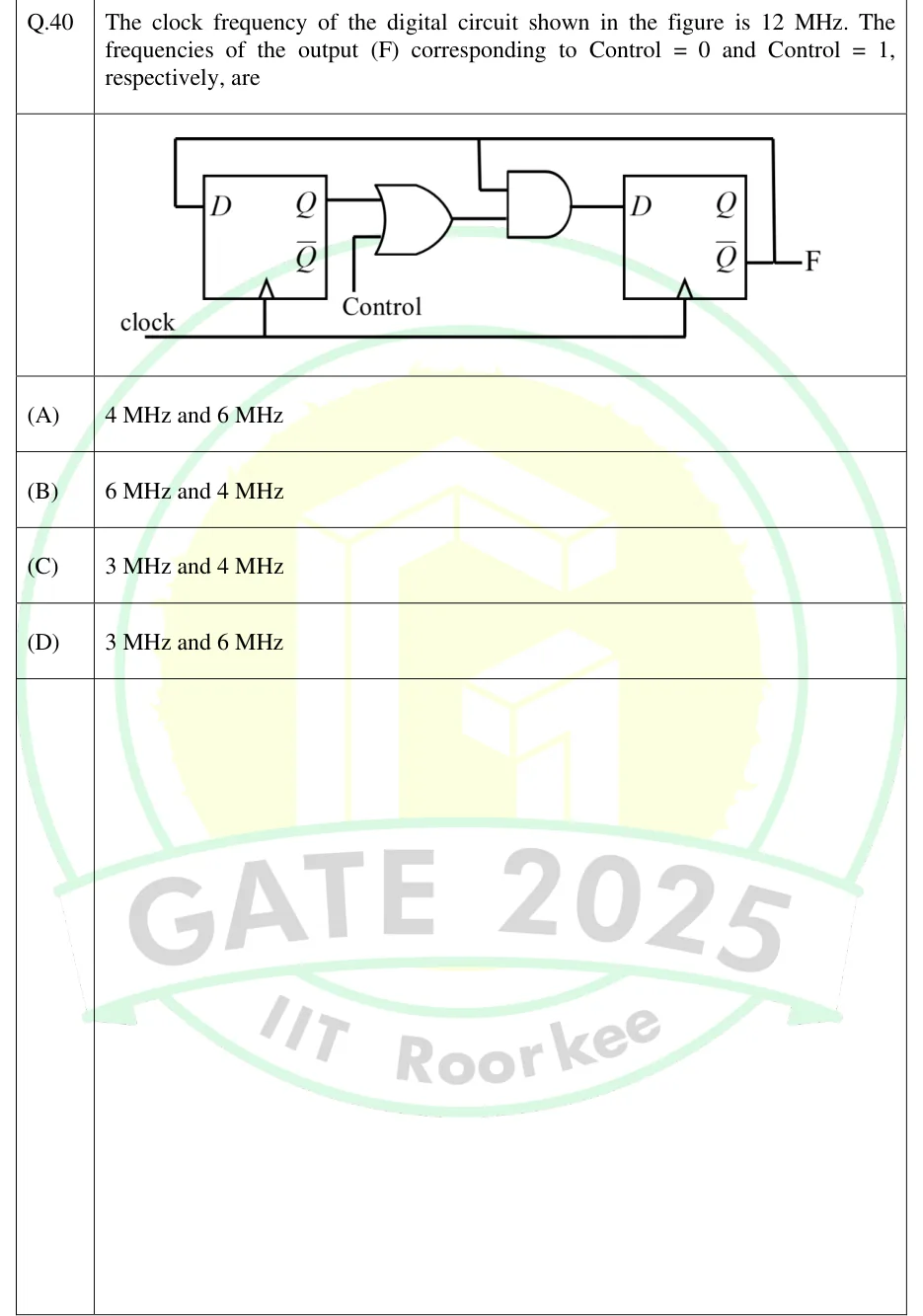
GATE 2025 IN question 40: Two positive-edge-triggered D flip-flops, FF1 (left) and FF2 (right), share one clock line labelled 'clock'…Tap to open full size
Figure from the GATE 2025 IN paper. It is part of the question.
Figure description

Two positive-edge-triggered D flip-flops, FF1 (left) and FF2 (right), share one clock line labelled 'clock' (edge-triggered clock inputs marked with a triangle on both). FF2's complemented output Q_2 is the circuit output F. A feedback wire from Q_2 (F) runs up across the top and back to the D input of FF1, so D_1 = Q_2; the same top wire has a branch that goes down into one input of a 2-input AND gate. A 2-input OR gate takes Q_1 (true output of FF1) and an external input labelled 'Control'. The OR output is the second input of the AND gate. The AND output drives the D input of FF2, so D_2 = Q_2 (Q_1 + Control). Q_1 is unconnected.

  1. (A)

    4 MHz and 6 MHz

  2. (B)

    6 MHz and 4 MHz

  3. (C)

    3 MHz and 4 MHz

  4. (D)

    3 MHz and 6 MHz

Answer and solution

ANSWER

(A) 4 MHz and 6 MHz. With Control = 0 the circuit is a mod-3 counter, so F = 12/3 = 4 MHz. With Control = 1, FF2 toggles on every clock edge, so F = 12/2 = 6 MHz.

Official answer: ASource: Official answer key, GATE 2025 IN (IIT Roorkee)

  1. Read the next-state equations off the figure. Overline means complement, and stands for Control. , , and the output is . Both flip-flops share the clock, and for a D flip-flop .

  2. Control = 1: , so . FF2 is wired as a toggle flip-flop and changes state on every clock edge, whatever is.

  3. A toggling output completes one full cycle every 2 clock periods, so it divides the clock by 2: .

  4. Control = 0: and . Trace the states with . From : , , so the next state is . From : , , so the next state is . From : makes both D inputs 0, so the next state is .

  5. The unused state also has , so and it goes to . Whatever state the circuit starts in, it ends up in the 3-state cycle .

  6. Over one cycle reads , so it repeats every 3 clock periods (duty cycle ): .

  7. So F is 4 MHz for Control = 0 and 6 MHz for Control = 1, which is option (A).

KEY IDEA

Write the D-input equations and trace the state sequence. The output frequency is the clock frequency divided by the number of clock periods before F repeats. With Control = 1 the OR gate is forced to 1 and FF2 becomes a toggle flip-flop (divide by 2). With Control = 0 the feedback from gives the 3-state cycle 00 -> 10 -> 11 (divide by 3). The unused state 01 falls into that cycle.

WATCH OUT FOR

Assuming two flip-flops always make a mod-4 counter and dividing by 4 (3 MHz, options C and D), without tracing the states. Another is swapping the order the question asks for (Control = 0 first), which gives option (B).

From the GATE 2025 IN paper. Every question of this paper · Download the full paper · All 30 Sequential questions, with notes

More Sequential questions