
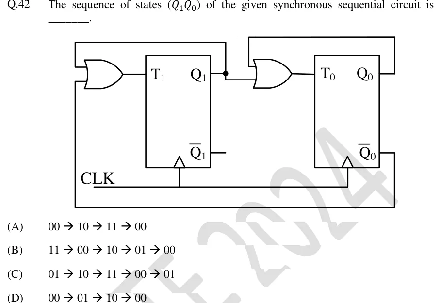
The sequence of states of the given synchronous sequential circuit is ________.
 Tap to open full size
Figure description
Two positive-edge-triggered T flip-flops share a common clock line CLK (the clock inputs are drawn with a triangle and no bubble). Flip-flop 1 (left) has input T_1 and outputs Q_1 and Q_1; Q_1 is not connected to anything. Flip-flop 0 (right) has input T_0 and outputs Q_0 and Q_0. OR gate 1 drives T_1. Its top input is fed back from Q_1: a wire leaves the junction dot on the Q_1 output, goes up, runs left and comes down into the gate. Its bottom input is Q_0: a wire leaves Q_0, goes right, down, left along the bottom of the drawing and up into the gate. So T_1 = Q_1 + Q_0. OR gate 2 drives T_0. One input is Q_1, taken straight from the junction dot. The other is Q_0, fed back through a wire that goes right from Q_0, up, left along the top and down into the gate. So T_0 = Q_1 + Q_0. There are no external inputs other than CLK.
- (A)
00 → 10 → 11 → 00
- (B)
11 → 00 → 10 → 01 → 00
- (C)
01 → 10 → 11 → 00 → 01
- (D)
00 → 01 → 10 → 00