
Which one of the following statements is true about the digital circuit shown in the figure
 Tap to open full size
Figure description
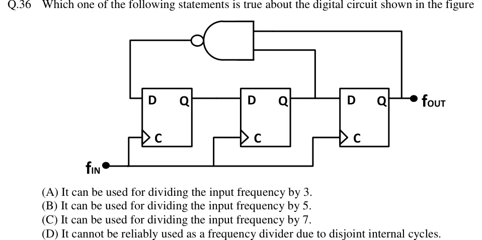
Three D flip-flops sit side by side. The figure does not name them; this solution calls them FF1, FF2 and FF3 from left to right. Each has a D input, a clock input C and one output Q. The clocks are edge-triggered (triangle symbol, no inversion bubble), so they trigger on the positive edge. All three clock inputs C are tied to one input, f_IN. Q of FF1 drives D of FF2, Q of FF2 drives D of FF3, and Q of FF3 is the circuit output f_OUT. A 2-input NAND gate sits above the flip-flops, drawn facing left with its bubble on the output. One input comes from Q3 (the f_OUT line) and the other from Q2 (the line from Q2 to D3). The NAND output goes back to D of FF1. So D1 = NAND(Q2, Q3), D2 = Q1 and D3 = Q2.
- (A)
It can be used for dividing the input frequency by 3.
- (B)
It can be used for dividing the input frequency by 5.
- (C)
It can be used for dividing the input frequency by 7.
- (D)
It cannot be reliably used as a frequency divider due to disjoint internal cycles.