
IAE Academy

ISRO EC 2025 Q.37: solution and answer

ISRO 2025 · ECQ.37 · 1 mark · MCQ

The switch in the circuit has been in position 'a' for a long time. At t = 0, the switch is moved to position 'b'. The initial voltage on the capacitor, the final voltage on the capacitor, the time constant for t > 0 are respectively :
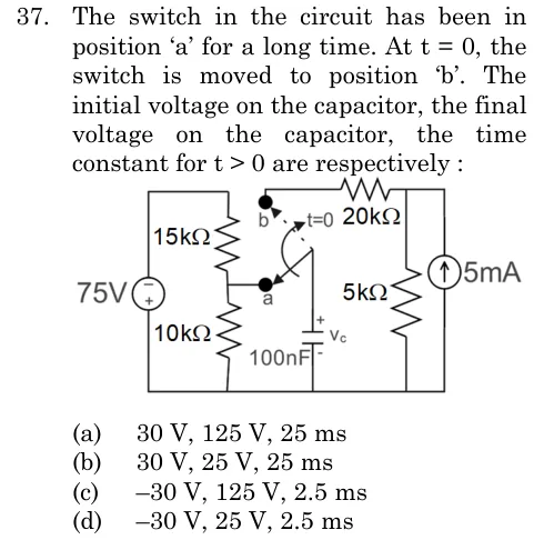
ISRO EC 2025 question 37: A 75 V source on the left with its + terminal at the bottom (the + sign is in the lower half of the circle).Tap to open full size
Figure from the ISRO EC 2025 paper. It is part of the question.
Figure description

A 75 V source on the left with its + terminal at the bottom (the + sign is in the lower half of the circle). A series divider of 15 kOhm (upper) and 10 kOhm (lower) is connected across the source; its midpoint is wired to contact 'a' of a single-pole double-throw switch. The switch pivot goes to the top plate of a 100 nF capacitor, marked + and labelled Vc, whose bottom plate joins the bottom rail. Contact 'b' (switch moved at t = 0) connects through a 20 kOhm resistor to the top-right node, where a 5 mA current source (arrow pointing up) and a 5 kOhm resistor are in parallel between that node and the bottom rail.

  1. (A)

    30 V, 125 V, 25 ms

  2. (B)

    30 V, 25 V, 25 ms

  3. (C)

    -30 V, 125 V, 2.5 ms

  4. (D)

    -30 V, 25 V, 2.5 ms

Answer and solution

ANSWER

Initial voltage , final voltage , time constant : option (d).

Official answer: DSource: ISRO's final answer key of 15 May 2026

  1. For the circuit is in steady state with the switch at 'a'. The capacitor carries no current, so the 15 kΩ and 10 kΩ resistors form a simple divider, and the capacitor sits across the lower 10 kΩ resistor. The magnitude of the voltage across the lower resistor is .

  2. Polarity: the + terminal of the 75 V source is on the bottom rail. The divider midpoint (the capacitor's marked + plate) is therefore 30 V below the bottom rail, so . A capacitor voltage cannot change instantly, so .

  3. For the switch is at 'b': the source and divider are disconnected, and the capacitor is in series with the resistor, across the parallel pair formed by the current source and the resistor.

  4. Final value: in steady state the capacitor carries no current, so no current flows in the resistor and there is no drop across it. The whole flows (upward, into the top-right node) through the resistor, so .

  5. Time constant: set the current source to zero (open circuit). The capacitor then sees in series with , so .

  6. The initial voltage is , the final voltage is and , which is option (d). Options (a) and (b) need , i.e. ; options (a) and (c) need a final value of , i.e. across the current source.

KEY IDEA

A capacitor voltage is continuous, so take the initial value from the old steady state (with its sign from the polarity marks) and the final value and time constant from the new circuit alone: open the capacitor for the final value, and switch off the sources (current source open) to find the resistance for the time constant.

WATCH OUT FOR

Ignoring the source polarity and writing the initial voltage as , or using the full with the in parallel or forgetting the in the final-value step (giving ). Also, leaving the out of the time-constant resistance (it is in series with the once the current source is open).

From the ISRO EC 2025 paper. Every question of this paper · The full paper (PDF, ISRO) · All 2 ISRO Transients questions, with notes