
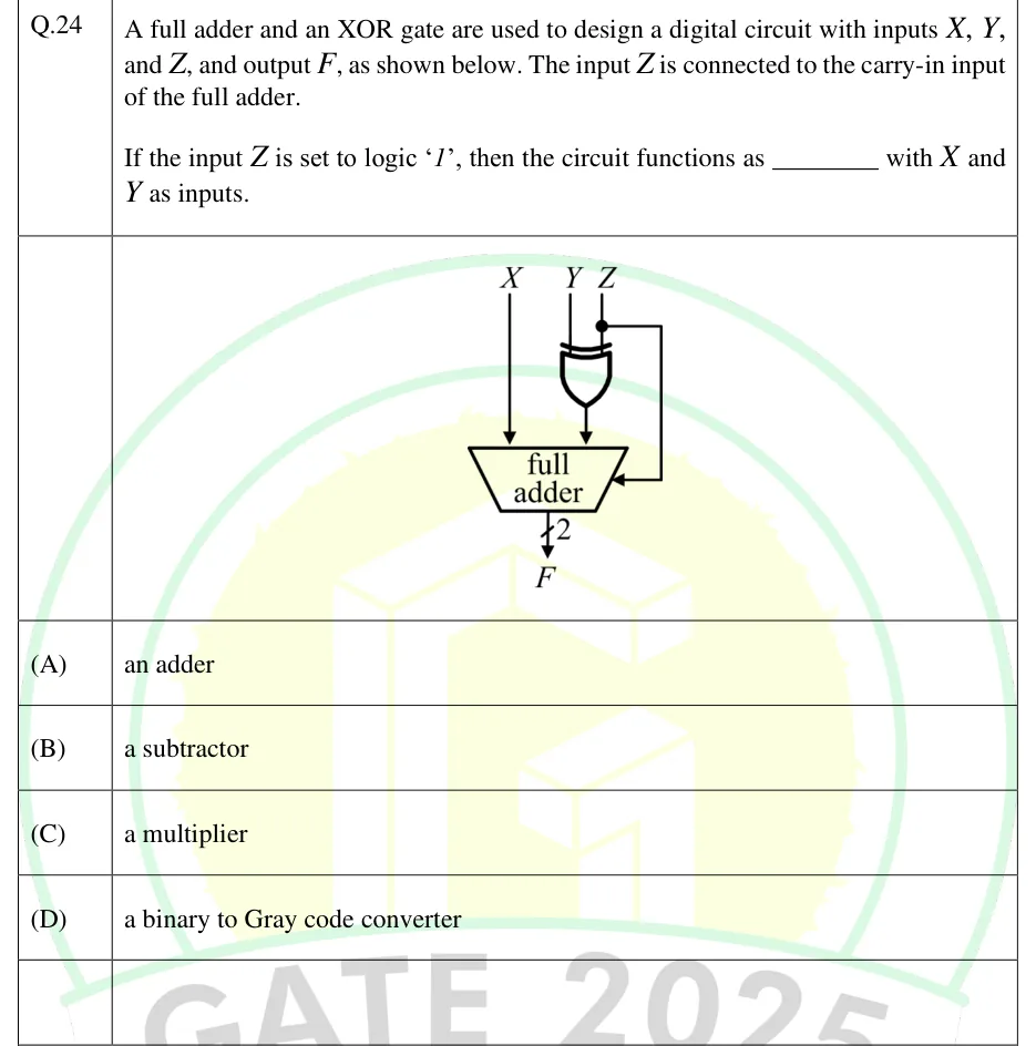
A full adder and an XOR gate are used to design a digital circuit with inputs , , and , and output , as shown below. The input is connected to the carry-in input of the full adder.
If the input is set to logic '1', then the circuit functions as ________ with and as inputs.
 Tap to open full size
Figure description
Three inputs X, Y, Z enter from the top. X goes straight down into the left operand input of a block labelled "full adder" (drawn as a trapezoid, wide edge on top). Y and Z are the two inputs of a 2-input XOR gate; the XOR output goes into the right operand input of the full adder. Z also branches off at a junction dot above the XOR gate and runs round the right side into the full adder's side input, which is its carry-in. The full adder's output is a 2-bit bus (a slash marked 2), labelled F, which carries the sum and the carry-out.
- (A)
an adder
- (B)
a subtractor
- (C)
a multiplier
- (D)
a binary to Gray code converter