
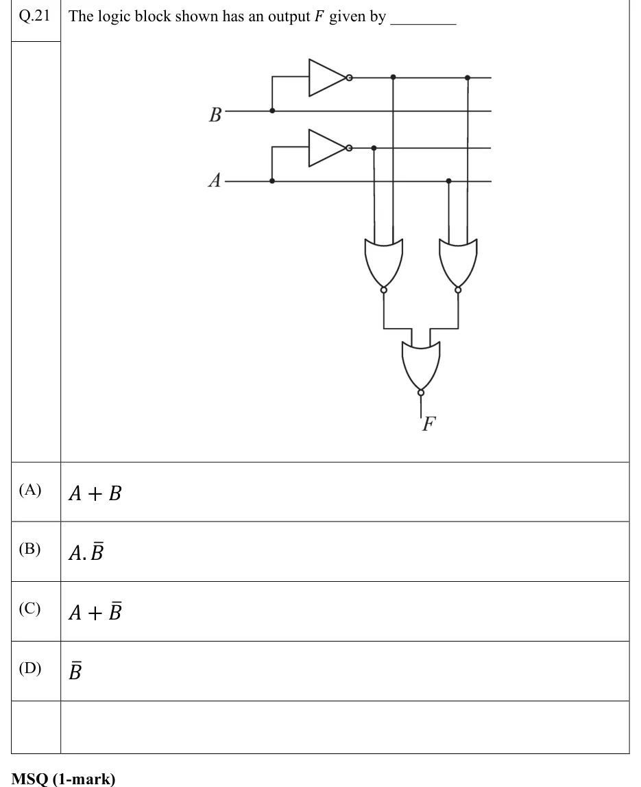
The logic block shown has an output given by ________
 Tap to open full size
Figure description
Two inputs, B (upper) and A (lower), enter from the left as horizontal lines. From left to right the circuit runs four horizontal rails, top to bottom: (1) B, the output of a NOT gate whose input is tapped from the B line; (2) B; (3) A, the output of a NOT gate whose input is tapped from the A line; (4) A. Two 2-input NOR gates sit below the rails. Left NOR gate: one input is tapped (dot) from the A rail and the other from the B rail, so its output is A+B. Right NOR gate: one input is tapped (dot) from the A rail and the other from the B rail, so its output is A+B. The outputs of both NOR gates feed a third 2-input NOR gate, whose output is F. Each gate is drawn as an OR shape with an output bubble, so all three are NOR gates.
- (A)
- (B)
- (C)
- (D)