
IAE Academy

GATE 2026 EE Q.45: solution and answer

GATE 2026 · EEQ.45 · 2 marks · MCQ

The digital circuit shown has 3 inputs (, , and ).

[Figure]

The simplified logical expression for the output (OUT) is:
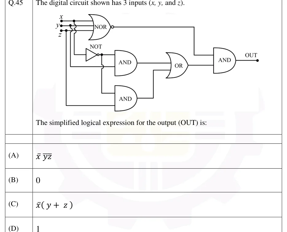
GATE 2026 EE question 45: Three inputs x, y, z enter from the left on three horizontal lines, x on top, then y, then z.Tap to open full size
Figure from the GATE 2026 EE paper. It is part of the question.
Figure description

Three inputs x, y, z enter from the left on three horizontal lines, x on top, then y, then z. All three lines go straight into a single 3-input NOR gate at the top. Three vertical wires leave these input lines at junction dots: a tap on the x line runs down, crossing the y and z lines with jumps (no connection), to the input of a NOT gate, whose output is x'. A tap on the y line runs down, crossing the z line with a jump, to the lower input of the first 2-input AND gate. A tap on the z line runs down to the lower input of the second 2-input AND gate. The NOT output (x') has a junction dot: it feeds the upper input of the first AND gate, and a vertical branch from it runs down (jumping over the y wire) to the upper input of the second AND gate. So AND1 has inputs x' and y, and AND2 has inputs x' and z. The outputs of AND1 and AND2 are the two inputs of a 2-input OR gate. The OR output and the NOR output are the two inputs of a final 2-input AND gate, whose output is OUT.

  1. (A)

  2. (B)

  3. (C)

  4. (D)

Answer and solution

ANSWER

OUT for every input, so the answer is (B) .

Official answer: BSource: Official answer key, GATE 2026 EE (IIT Guwahati)

  1. Notation: an overbar means complement (so is NOT ). Read each gate from the junction dots. A jump (a small arc) where two wires cross means they are NOT connected.

  2. NOR gate, inputs : (De Morgan's theorem).

  3. NOT gate, input tapped from the line: its output is . The junction dot on that output sends to both AND gates.

  4. AND gate 1 has inputs and , so its output is . AND gate 2 has inputs and , so its output is .

  5. OR gate: (take out the common factor with the distributive law).

  6. Final AND gate: This uses and .

  7. Check: only when . For that input . So the two inputs of the final AND gate are never both 1, and OUT is 0 for every input combination. Answer: (B).

KEY IDEA

The NOR output is 1 only when . The OR output needs or to be 1. The final AND gate needs both to be 1 at once, which never happens, so OUT is the constant 0.

WATCH OUT FOR

Stopping at the OR gate and choosing (C) , even though that signal still passes through the final AND gate with the NOR output. A second mistake is misusing De Morgan and writing as (option A); the correct form is . A third is treating the wire jumps as connections, which puts the wrong input on the AND gates.

From the GATE 2026 EE paper. Every question of this paper · Download the full paper · All 22 Boolean logic questions, with notes

More Boolean logic questions